MMI defekt: Leiterplatte/ Platine einzeln?
Hallo zusammen,
ich habe so einiges jetzt hier im Forum durchsucht, habe aber keine Lösung zu meinem Problem gefunden:
Bei mir ist Flüssigkeit auf die Leiterplatte / Platine gelaufen. Also von oben durch's MMI. Nach dem Ausbau der Mittelkonsole sah man, dass die Platine z.T. verätzt ist. Sie wurde gereinigt und wieder eingebaut, der Fehler bleibt aber (die rechte obere Taste neben dem "Drehknopf" in der Mitte hängt und so lassen sich z.B. keine CDs mehr aus dem Wechsler auswählen.)
Ein neues MMI (mit Navi /Tel Tasten) kostet um die 550€ mit Mwst.
Kann man die defekte Platine auch einzeln erwerben? Also bei Audi selber wohl eher nicht, aber vielleicht gibt es noch andere Bezugsquellen.
Gruß
Anja - littlesister
Beste Antwort im Thema
Also, der SC111345CFU ist ein Microcontroller von Freescale (ehem. Motorola) und ohne Software völlig wertlos und damit nur beim Hersteller der Leiterplatte austauschbar (wenn er denn wirklich defekt sein sollte) Die grün eingekreisten Bauteile sind LED's der Fa. Osram. Manchmal macht es Sinn statt Dioden lieber LED's einzusetzen (verschiedene Geräte mit selber Leiterplatte oder auch wegen der Eigenschaften der LED) damit diese dann nicht durchleuchten ist da wohl ein Klecks Kleber drauf.
Das Hilft aber alles nicht bei der Reparatur. Meistens tritt bei Flüssigkeitseintritt ein Kurzschluss am µC aufgrund der kleinen Strukturen auf und zerstört I/O's
Gruß
Matthias
74 Antworten
@ Ukrainian: You have post - PN🙂
Je weiter alle Bauteile in der Funktion u ihren Anschlüssen dekodiert werden, umso rätselhafter wird es. Schwitz, ob das noch weiter Sinn macht, da Zeit zu investieren, strebt langsam einer Antwort entgegen.😠
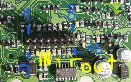
Für einen Trockentest wird noch die Anschlussbelegung des 16-poligen-Connectors gesucht. GND liegt an Pin 8, aber wo ist der Plus-Anschluss? Sowas ist "normalerweise" nicht das Problem, man sucht nach größeren Elkos, Spannungsreglern u.ä. und findet via diverse Leiterbahnen den Plus-Anschluss. Aber hier ist fast nichts normal, nicht mal über hochomige Einstellungen (2k) läßt sich da was ermitteln. Bislang einzig in Frage kommt Pin 10, von da gehts aber für eine solche Schaltung ungewöhnlich erst über einen 470 Ohm-R weiter u dann auch noch auf einen Kleinsignal-Transistor und - ach ja - dahinter verlaufen die Signale im Sand. Unterhalb des Connectors liegt ein Spannungsregler-IC (SRI). Die Fa. Infineon gibt da auch ein schönes Datenblatt aus. Also alllllessss klaaarrrrrr!
Nix! Auch von hier ist außer dem GND-Anschluss nur das Band zu hören: Kein Anschluss unter dieser......über irgendwelche Leiterbahnen. Gibt man auf den vermuteten Pin 10 des C mal vorsichtig 3 Volt, fließ kein Strom - was noch in Ordnung sein könnte - aber gettz: Die Spannung am Ausgang des SRI ist höher als die Eingangsspannung.😰
Ohne Schaltplan ist das eine elende Sucherei in einer 3-Layer-Platine, und leider sind es auch mehr als 5 Bautteile!😕 Will sich jemand mit Hinweisen, die zur Ergreifung des .......... Plus-Anschlusses führen, ein paar Trocken-Blumen verdienen?
Gruß, lippe1audi
Zitat:
Original geschrieben von lippe1audi
@ Ukrainian: You have post - PN🙂Je weiter alle Bauteile in der Funktion u ihren Anschlüssen dekodiert werden, umso rätselhafter wird es. Schwitz, ob das noch weiter Sinn macht, da Zeit zu investieren, strebt langsam einer Antwort entgegen.😠
Für einen Trockentest wird noch die Anschlussbelegung des 16-poligen-Connectors gesucht. GND liegt an Pin 8, aber wo ist der Plus-Anschluss? Sowas ist "normalerweise" nicht das Problem, man sucht nach größeren Elkos, Spannungsreglern u.ä. und findet via diverse Leiterbahnen den Plus-Anschluss. Aber hier ist fast nichts normal, nicht mal über hochomige Einstellungen (2k) läßt sich da was ermitteln. Bislang einzig in Frage kommt Pin 10, von da gehts aber für eine solche Schaltung ungewöhnlich erst über einen 470 Ohm-R weiter u dann auch noch auf einen Kleinsignal-Transistor und - ach ja - dahinter verlaufen die Signale im Sand. Unterhalb des Connectors liegt ein Spannungsregler-IC (SRI). Die Fa. Infineon gibt da auch ein schönes Datenblatt aus. Also alllllessss klaaarrrrrr!
Nix! Auch von hier ist außer dem GND-Anschluss nur das Band zu hören: Kein Anschluss unter dieser......über irgendwelche Leiterbahnen. Gibt man auf den vermuteten Pin 10 des C mal vorsichtig 3 Volt, fließ kein Strom - was noch in Ordnung sein könnte - aber gettz: Die Spannung am Ausgang des SRI ist höher als die Eingangsspannung.😰
Ohne Schaltplan ist das eine elende Sucherei in einer 3-Layer-Platine, und leider sind es auch mehr als 5 Bautteile!😕 Will sich jemand mit Hinweisen, die zur Ergreifung des .......... Plus-Anschlusses führen, ein paar Trocken-Blumen verdienen?
Gruß, lippe1audi
Look at the picture in the attachment (+) pin7, gnd pin8. Diodes on picture is S2b
http://www.dacosemi.com.tw/userfiles/file/STD-SMD-GPP/S2A-S2M.pdfZitat:
Teilweise original geschrieben von Ukrainian
Look at the picture in the attachment (+) pin7, gnd pin8
Thanks a lot ! 🙂 We are one step forwards ! Now it's possible, to observe the circuit under "live"-conditiones.🙂 At first, the voltage at regulator ist perfect at 5 Volt. At start, the circuit takes about 35 mA, after about 20 seconds this go down nearly to 0 ore maybe 1 mA. Next, all the switches are working fine, each preasure of a switch starts the circuit, most of them has the effect, that the circuit is working for 3 seconds, and then go's sleeping again. Thats nice, the LM 2902, the IC with 4 operation amplifiers in it, sleeps most time, he only works at start and then at pressing a switch.
Next work is to proof the IR-Diodes, but this is for the next day.
Ukrainian, your writings are very helpful. A very big "Thank you" goes to the Ukraine.😎
Greetings, lippe1audi
Zitat:
Original geschrieben von lippe1audi
Thanks a lot ! 🙂 We are one step forwards ! Now it's possible, to observe the circuit under "live"-conditiones.🙂 At first, the voltage at regulator ist perfect at 5 Volt. At start, the circuit takes about 35 mA, after about 20 seconds this go down nearly to 0 ore maybe 1 mA. Next, all the switches are working fine, each preasure of a switch starts the circuit, most of them has the effect, that the circuit is working for 3 seconds, and then go's sleeping again. Thats nice, the LM 2902, the IC with 4 operation amplifiers in it, sleeps most time, he only works at start and then at pressing a switch.Zitat:
Teilweise original geschrieben von Ukrainian
Look at the picture in the attachment (+) pin7, gnd pin8
Next work is to proof the IR-Diodes, but this is for the next day.Ukrainian, your writings are very helpful. A very big "Thank you" goes to the Ukraine.😎
Greetings, lippe1audi
I think that the best solution would be to install the block in the car and try to include. Perhaps in the block have feedback devices and therefore work not long. In my case, after the repair of power supply connections, after installation in the car block have work with no problems
Ähnliche Themen
The only thing that block i fixed is already work in my friends car and all the advice you give from my memory 🙂 I helped my friend to save money. In Ukraine, the price of a new block 700 euro 🙂 This is a average wage of an engineer 🙂
Hallo.
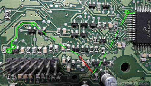
Ist hier vielleicht jemand der mir sagen könnte (ohne Gewähr) wohin der auf dem Bild Markierte Pfad führt, ich vermute dass diese Leiter Bahn hin ist.
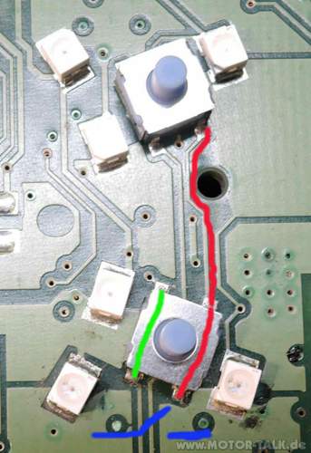
Mit Gewähr kann ich dir sagen, wohin was führt, vorausgesetzt, du hast die richtige Stelle markiert. Interpretiert habe ich den Pfeil, dass du den rechten unteren Pin des Schalters meinst.
Diese Schalter haben insgesamt vier Anschlüsse und innen drin einen Schalter. Auf meinem Bild habe ich versucht, das zu verdeutlichen. Deine markierte Stelle gehört zu den beiden rechten Anschlüssen des "rechten Pols" des Schalters, hier rot markiert. Wenn der Schalter schaltet, dann verbindet er den rechten, roten Teil mit dem linken, grünen Teil.
Das Blaue soll nur die Funktion als Schalter kennzeichnen, das ist keine Leiterbahnverbindung.
Falls du den weiteren Verlauf auch noch brauchst, oder eine andere Leiterbahn meinst, melde dich halt. Bin heute Vormittag in der Werksatt und schaue hier gelegentlich mal rein.
Grüße, lippe1audi
Hello,
I have a problem with this MMI from an Audi Q7. There was some juice spilled on him.
I can't find this link. Can anyone help me?
Zitat:
@cataling3 schrieb am 15. Juli 2016 um 08:59:14 Uhr:
I can't find this link. Can anyone help me?
What do you mean with " this link"?
We have one spezial forum for Audi Q7:
http://www.motor-talk.de/forum/audi-q7-b318.htmlBut the problem with your MMI will be the same. You should read just this examination in our Audi A6-Forum, just where you are:
http://www.motor-talk.de/.../...atte-platine-einzeln-t4322485.html?...
There are described solutions for this problem. Try to clean it and to dry up very long and exactly.
Greetings, lippe1audi
Thanks for the quick response.
The area that I colored it is a crossing between wiring layers. The problem is that the passage is oxidized very bad and do not know where should reach so I could retrace.
I could not find any wiring diagram.
Yesterday I cleaned the plate with isopropyl alcohol, and today I have to redo them electrical routes.
Thank you,
Catalin
I bag your pardon, i did not noticed your picture. I habe one MMI-plate here, and it seems to be the same. I try to follow the connections, but it takes time. Maybe in one our.....
Greetings, lippe1audi
Thank you very much!
These are the routes I could find them and recover them.
What the hell is that!😰
I found connections also, but some other! Look to my pictures!
Greetings, lippe1audi
Thank you for your help.
This is the connection which is broken on my board. I digged in the board until the second layer and I found it.
Thank you again for your help,
Catalin
Hallo "cataling3" !
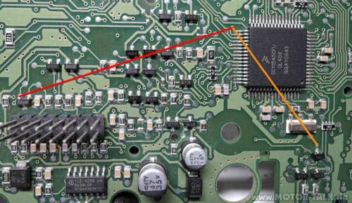
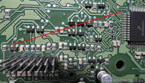
We two are right with our looking for connections! See the picture, the red one i found, the orange one you found, both are the same, because connected. Its very interest, to look in such platine.
You had soldered some more cables. Please led us know, if you rebuild your MMI-Platine in your car and if its function!
Greetings, lippe1audi